This will show you a typical clutch replacement and help you with the little nuances which will give you the best result. A clutch is constructed using asbestos so use a mask before removing the clutch disc. Gloves and protective eyewear are a good idea as well. There will be several subsequent guides that will need to be performed before the clutch can be replaced which are listed below:
Jack up and support the car on jack stands
Remove the exhaust system (some models)
Remove the driveshaft (rear wheel drive)
Remove CV axle (front wheel drive)
Manual transmission removal
1. Remove the Clutch: Once the above jobs have been done it's time to inspect and remove the clutch pressure plate. The picture below shows what it looks like once the transmission has been removed which exposes the clutch assembly that is mounted onto the flywheel at the rear of the engine. Again this part deals with asbestos so an air mask is recommended.
The pressure plate will be held onto the flywheel by 10 12mm, 13mm or 14mm bolts in most cases. When you start to undo the bolts the flywheel will want to move and turn the engine over so you will need to break the bolts loose by applying leverage inward or outward from the flywheel. An impact gun also works well for this. Do not remove all of the bolts at once because the pressure plate traps the clutch disc which can be heavy and can fall causing an injury. As the last bolts are undone have an extra hand to control both the pressure plate and disc. The pressure plate will start to move outward from the flywheel as the the bolts are undone.
SPONSORED LINKS
While the last bolts are being removed keep your hands on the disc and plate to control these parts. Support the disc while using a finger which is a good method of holding the disc onto the pressure plate.
Once the bolts have been removed the pressure plate may still be held onto the flywheel with 3 or more alignment dowels. Gently work the pressure plate from the flywheel using a standard screwdriver until free.
SPONSORED LINKS
2. Inspect Clutch Wear: The clutch disc is the part that wears down much like a brake pad, in fact the clutch disc has brake pad material on either side of it which is held on by rivets. When this lining wears it allows the rivets to contact the flywheel or pressure plate which causes the clutch to slip.
3. Check the Flywheel: The clutch mating surface of the flywheel will now be exposed. You are looking for extreme heat checks, hot spots and cracks which are a sign the clutch was slipping for a long period of time and will warrant the flywheel's replacement. The flywheel below is what a the typical wear pattern looks like during a clutch replacement and can be re-machined which must be done anytime you are servicing the clutch. If this step is skipped when the new clutch is installed you will have a good chance that it will chatter when the clutch pedal is released and the job will need to be redone.
SPONSORED LINKS
4. Replace Pilot Bearing: On rear wheel drive and some front wheel drive cars the clutch will have a pilot bearing which is designed to support the input shaft of the stick shift transmission. If this bearing locks up or becomes worn out it allows the input shaft to wonder and will cause the clutch to not disengage. The pilot bearing should be replaced during the clutch service.
5. Match the New Clutch: Place the old clutch next to the new clutch on a table. Check the diameter of the disc and the surface area of the clutch material. Also look at the pressure plate height with one next to the other, they should be fairly close. This will present a problem if they are way off in the operation of the clutch, either not releasing or engaging.
Before re-installing the clutch disc back onto the flywheel fit the disc over the input shaft of the transmission. It should slide onto the shaft with little resistance. This is too help avoid a problem when reinstalling the transmission.
SPONSORED LINKS
6. Install the New Clutch: This part is very important! The clutch disc can go onto the pressure plate in either direction but only one direction is correct. The part of the disc that is protruding outward must go toward the pressure plate or the clutch will not release so it's important to install the disc in the proper direction. Also it is important to use brake cleaner to remove grease and dirt from the flywheel and pressure plate clutch contact surfaces before installation.
Gently install the new clutch disc and pressure plate onto the alignment dowels of the newly resurfaced flywheel while installing the mounting bolts by hand. Leave the pressure plate bolts a little lose so the pressure plate can move around. This is so you can insert the clutch alignment tool included in the clutch kit.
SPONSORED LINKS
Locate the clutch alignment tool included in the clutch replacement kit. This is needed to line up the clutch disc to the pilot bearing so the transmission can be easily reinstalled.
With the clutch disc loose position and install the clutch alignment tool into the clutch disc and pilot bearing. Slightly tighten the bolts further to hold the disc in place and move the tool in a circular motion. It will give some resistance in all directions and you want to find a good center point. This means the disc is in the middle of the pressure plate.
Tighten the pressure plate evenly and slowly in a star pattern using a ratchet. Do not tighten any one bolt all at once and do not use air tools. This will bend the pressure plate and cause the clutch not to disengage. Work your way around the pressure plate slowly tightening several times until completely tight. You will notice the fingers of the pressure plate traveling inward as you tighten the bolts. You want this progression to be as even as possible. If this step is not done correctly the clutch will not release properly which can cause hard shifting. Finish tightening the bolts to factory torque specifications which is usually between 25 and 30 foot pounds. Again the flywheel will try and turn the engine over so tighten inward.
SPONSORED LINKS
Remove the clutch alignment tool and recheck all of the mounting bolts.
7. Replace Throughout Bearing: The throwout bearing is designed to push the fingers of the pressure plate inward to disengage the clutch. When these fingers are out or with no pressure on them the clutch is engaged. When replacing the clutch assembly it is highly advised to replace the throwout bearing because it has a high failure rate. Some throwout bearings are attached to the clutch slave cylinder which should be replaced as a unit.
8. Clutch Break-in and Adjustment: Once the transmission has been reinstalled slowly pump the clutch pedal until normal pedal operation is present. Watch and add clutch fluid (brake fluid) in the process. After the repair start the engine and push the clutch pedal down completely while shifting the transmission through its gears. It's normal for this operation to be a little rough while the clutch is in it's "break in" period. Normal shifting characteristics should return after a few miles.
Wednesday, 26 July 2017
Wednesday, 12 July 2017
How to replace the rear wheel bearing?
Wheel bearing failure can be catastrophic so it is important to change them when you first start experiencing problems. Typical symptoms include, but are not limited to, the following:
Rumbling sensation when braking or driving along.
Excessive noise from the wheels when braking.
Poor handling when braking.
Knocking or rumbling when cornering.
To check your wheel bearings, jack up the rear of the car and grasp the wheel at the top and bottom. Rock the wheel back and forth and look for play in the bearings. Spin the wheel as well. If it sounds rough, then the bearings are probably on their way out.
In this guide, we are going to replace the wheel bearing and hub assembly. The rear hub assembly is available from smart at a cost of around £70.
To replace the assembly, ensure that you are parked on level ground. Chock the front wheels, slacken the wheel bolts, jack up the rear of the car and remove the wheel.

Support the rear of the car on axle stands. Use the subframe and not the De Dion tube as we need this free to move.
Unfortunately the bolts that secure the rear hub assembly are obstructed by the driveshaft. Therefore, the driveshaft needs to come out. To do this, remove the bolts holding the lower arms of the tie bar.

Use an E16 socket on the bolt. Hold the nut on the rear with a 18mm ring spanner (if you have a mk4 or earlier, you won't have to hold the nut as it is welded to the axle). Support the De Dion tube beneath the rear brake drum with the jack to prevent the bolt from binding. There will be a small amount of tension released as the bolt comes out.

Carefully lower the De Dion tube on the jack. Check the axle stands haven't moved. Now repeat for the other side. Both tie arms need to be free.

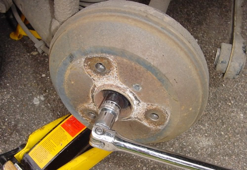
Use a 13/16 AF imperial socket to remove the long driveshaft bolt as shown. You will need a long bar to do this as it is held tight.

Undo the bolt on the front of the brake drum with a TX30 bit. Release the handbrake before you try and remove the drum!

Pull the driveshaft out of the back of the hub. You may need to pull the De Dion tube towards you to make enough space. Make sure the car is supported well before you do this.

You can now access the four E14 bolts on the back of the hub.

Remove all four bolts, hold the backing plate for the rear brake and carefully pull the hub free from the car.

The hub has a lip on the back which stops it falling off as you remove the bolts.

As the hub becomes free, we used one of the bolts we removed to hold the brake backing plate to the axle. In this way, you avoid putting stress on the brake lines.

You can now replace your old hub with the new one.

the hub doesn't have a particular 'way up'. Just ensure you don't trap any dirt as you bolt the new hub through the axle and rear brake base plate.

Reassembly is the reverse of removal.
Torque settings:
E14 hub mounting bolts: 65Nm.
TX30 brake disk securing bolt: 6.5Nm.
13/16 AF Driveshaft Bolt: 30Nm + 90°.
Wheel bolts: 110Nm.
Rumbling sensation when braking or driving along.
Excessive noise from the wheels when braking.
Poor handling when braking.
Knocking or rumbling when cornering.
To check your wheel bearings, jack up the rear of the car and grasp the wheel at the top and bottom. Rock the wheel back and forth and look for play in the bearings. Spin the wheel as well. If it sounds rough, then the bearings are probably on their way out.
In this guide, we are going to replace the wheel bearing and hub assembly. The rear hub assembly is available from smart at a cost of around £70.
To replace the assembly, ensure that you are parked on level ground. Chock the front wheels, slacken the wheel bolts, jack up the rear of the car and remove the wheel.

Support the rear of the car on axle stands. Use the subframe and not the De Dion tube as we need this free to move.
Unfortunately the bolts that secure the rear hub assembly are obstructed by the driveshaft. Therefore, the driveshaft needs to come out. To do this, remove the bolts holding the lower arms of the tie bar.

Use an E16 socket on the bolt. Hold the nut on the rear with a 18mm ring spanner (if you have a mk4 or earlier, you won't have to hold the nut as it is welded to the axle). Support the De Dion tube beneath the rear brake drum with the jack to prevent the bolt from binding. There will be a small amount of tension released as the bolt comes out.

Carefully lower the De Dion tube on the jack. Check the axle stands haven't moved. Now repeat for the other side. Both tie arms need to be free.

Use a 13/16 AF imperial socket to remove the long driveshaft bolt as shown. You will need a long bar to do this as it is held tight.
Undo the bolt on the front of the brake drum with a TX30 bit. Release the handbrake before you try and remove the drum!

Pull the driveshaft out of the back of the hub. You may need to pull the De Dion tube towards you to make enough space. Make sure the car is supported well before you do this.

You can now access the four E14 bolts on the back of the hub.

Remove all four bolts, hold the backing plate for the rear brake and carefully pull the hub free from the car.

The hub has a lip on the back which stops it falling off as you remove the bolts.

As the hub becomes free, we used one of the bolts we removed to hold the brake backing plate to the axle. In this way, you avoid putting stress on the brake lines.

You can now replace your old hub with the new one.

the hub doesn't have a particular 'way up'. Just ensure you don't trap any dirt as you bolt the new hub through the axle and rear brake base plate.

Reassembly is the reverse of removal.
Torque settings:
E14 hub mounting bolts: 65Nm.
TX30 brake disk securing bolt: 6.5Nm.
13/16 AF Driveshaft Bolt: 30Nm + 90°.
Wheel bolts: 110Nm.
Subscribe to:
Posts (Atom)