Wednesday 13 May 2020

HOW TO RELEASE A BALL JOINT

YOU MUST REMOVE A BALL JOINT TO PERFORM OTHER REPAIRS
 
A ball joint is used to act as a universal swivel joint that connects the upper or lower control arms to the spindle which is where the axle bearing and wheel is supported. This joint is also responsible for allowing the steering to work as it is the bottom part of the pivot for the spindle. Constructed of a metal housing with a spherical metal ball, the ball joint is designed with the threaded stud attached at one end. This ball joint stud is designed with a slight taper which will lock into a tapered hole which offers a measure of strength when attaching the ball join to the spindle. The ball is trapped inside the housing with enough clearance to move freely without play. Grease is used to lubricant the joint which may have a Zerk fitting that is used to refill the joint at regular service intervals. Most cars today have non-serviceable joints which are equipped with enough grease to last the duration of the ball joint's usability.

To replace or perform repairs on or near the ball joint such as replacing a control arm or a CV axle the ball joint will need to be undone which means taking the nut off of the joint and applying pressure while striking the spindle or control arm bulk head with a hammer. Some ball joints have a cotter pin which is used as a safety device to keep the nut from coming off and the joint coming undone. Other designs have a self locking nut that doesn't require a cotter pin. The most difficult part of removing any ball joint is disconnecting the taper fit stud at the end of the joint. Some ball joints are made into the lower or upper control arm while in other applications the joint can be unbolted separately. It is strongly suggested to have the car aligned after replacing a ball joint.

WHAT GOES WRONG?
 
When the ball joint wears due to usage and the normal travel of steering and suspension parts the joint will have excessive play that will cause problems such as allowing the steering wheel to shake while driving and making popping and clicking noises as the car is being driven and going over bumps. Ball joint wear can also contribute to irregular tire wear.

LET'S GET STARTED
 
The car must be jacked up off the ground and supported on jack stands. You may need to remove the wheel to be able to access the ball joint more freely. There are two styles of ball joint, one faces downwards while the other faces upwards. Each are similar and will require different placement of the breaker bar to undo. We will demonstrate both styles in the guide. All ball joints connections are a tapper fit that must be released to come undone. This guide is for strut style of suspension which has the coil spring encapsulated within the strut. If this job is being done on a live spring style of suspension the lower control arm must be supported using a jack and then slowly lowered once the ball joint has been undone. A live spring suspension is one that has the spring pressed against the lower control arm. This spring is very strong so caution should be used when dealing with this spring.

1. Remove the Cotter Pin

A cotter pin is used to keep the connection between the ball joint and control arm in tact in case the nut comes loose. The nut in the image below is called a castle nut which has 6 places in which the cotter pin can hold the nut from moving. Use a pair of side cutters (dikes) to remove the cotter pin from the castle nut which will enable the nuts removal.


2. Loosen the Castle Nut

Use a 19mm to 22mm wrench or socket to loosen the nut by turning it counterclockwise. These nuts can be fairly tight so make sure the socket or wrench is squarely on the nut before applying pressure to avoid rounding and damaging the nut. Do not fully remove the nut, leave it on the stud about three turns to protect the stud threads when undoing the joint.


3. Release the Ball Joint Taper

Use a large pry bar and wedge it in-between the lower control arm and the spindle bulk head. Make sure the pry bar is in a solid place because you will need to apply pressure to undo the joint.

While applying force downward strike the lower control arm bulkhead to release the ball joint taper. This will take more than one hammer strike to get the ball joint to release in most cases. If you have trouble with this step have a helper apply additional pressure on the pry bar while using a larger hammer to make the strikes. This will "shock" the joint loose and you should feel a pop when the joint releases.

Once the ball joint has released finish removing the lower ball joint nut and continue with the repair. We will demonstrate the upward style of ball joint below.

After the cotter pin has been removed use a 22mm to 24mm wrench to remove the lower ball joint nut by turning it counterclockwise. It is okay if the steering turns during this step.

Once the nut is loose do not remove it completely. Leave the nut on the ball joint stud a couple of turns. This will protect the threads when disconnecting the joint.

Again wedge a large pry bar while apply downward pressure between the spindle bulk head and lower control arm. While still holding the pressure on the ball joint use a hammer to "shock" spindle bulkhead this time. It may take a couple hits of the hammer but hang in there until the ball joint taper releases.

When the ball joint taper joint releases, there will be a noticeable gap between the ball joint dust boot and the spindle. The gap between the ball joint nut and spindle will also be gone.


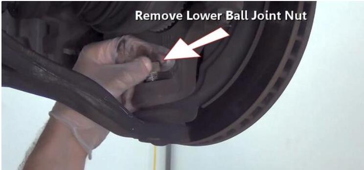
Now you can finish removing the ball joint nut.


4. Disconnect the Control Arm

Grasp the lower control arm while holding the spindle steady. Pull the lower control arm downward to disconnect it from the spindle. At this point the bottom of the spindle will be able to move around freely. This method will work for both upper and lower control arms.


Wednesday 6 May 2020

How to check spark plugs


In times past, one of the easiest maintenance items on a vehicle was checking and changing the spark plugs. That was before engine compartments became shrouded in emissions tubing and computerized sensors. If you’re lucky enough to have an automobile where the spark plugs are relatively easy to reach, take advantage of it. That’s because they offer telltale indications of what’s going on in the combustion chamber and the internal health of your engine.

Before you begin ratcheting out your spark plugs in search of suspicious symptoms, a few words of caution: First, be sure to check all of the plugs. There could be a serious problem brewing in just one cylinder that you wouldn’t want to overlook. Second, if your plugs indicate a problem related to the plug’s heat range or the plug is simply worn out, you can fix these problems with a new, and correct, set of plugs. If the diagnosis is more serious, though, and your plugs are oil-foiled because of a worn piston ring, new plugs won’t make the worn ring go away. Get the vehicle to your mechanic for the overhaul, and then replace the plugs.

The following is a comprehensive list of conditions that you may find useful when you are checking spark plugs:

Normal

When the engine is running the way it should, normal-reading plugs will look pretty much the same way they did when they were new and first screwed into the engine block.

Normal, but with red coating

The red coating is a result of the additives in lower-quality unleaded fuel and will be visible on the plug’s ceramic insulation. The red coating is not an indication of any engine problems.

Fuel fouled

Fuel-fouled plugs may have a shiny coating on the tip and side electrode, which may indicate a too-rich fuel mixture, ignition problems or a plug heat range that’s set too low. First, check to make sure your spark plugs have a heat range that is compatible with your engine (especially if you’ve made performance modifications). This information is available in your vehicle owner’s manual. To resolve the too-rich fuel mixture, have the fuel injection (or carburetor) adjusted to correct the air/fuel mix.

Detonation damage

This plug condition indicates that your engine timing is off and you probably need a tune-up. Another possibility is that the gasoline you’re using does not have a high enough octane rating. Again, check the owner’s manual to verify the manufacturer’s recommendation on octane level.Worn plug

This is an easy fix–replace the plug. Most plug manufacturers indicate the recommended service life on the packaging.

Carbon fouled

If your plug tip and side electrode are blackened, they have been running with too much fuel (or possibly too cool from a stuck-open thermostat). Other sources of the problem may include bad wiring or leaking injectors; in some cases the vehicle has been driven at too slow a speed for extended periods of time. The combustion process is not being allowed to have its natural burning-off, or cleaning, effect.

Preignition

The plug will reveal that the side electrode has been burned away from running too hot. The plug is firing too soon, not enough fuel is present in the air/fuel mixture or there isn’t enough fuel in the combustion chamber for a sound combustion event. Check your fuel injection and timing. Take quick action, because a plug in this condition is just short of falling completely apart.Oil ash fouled

Engine oil is getting to your plugs from worn piston rings or valve guides/seals. Get to your mechanic now.

Mechanical damage

A mechanically damaged plug will look as if it’s been beaten to death by its piston, an indication that it extended too far down into the combustion chamber.

The two most common spark plug problems are hot fouling and cold fouling. The “too hot” category includes the preignition and detonation damage. Some performance improvements may be the cause for this type of plug damage. If your vehicle has performance upgrades such as a high-output coil, ignition, exhaust or cams, these can alter the engine’s recommended plug heat range, so you should consider using a spark plug with a heat range lower than the manufacturer’s recommendations.

A few of the symptoms indicated by your spark plugs have simple fixes–others require the hands and expertise of a qualified mechanic. Eitherway, the main advantage to checking out your spark plugs is for a quick diagnostic tool that gives you a fairly good idea of how well your engine is performing.

Wednesday 29 April 2020

How to Replace a Door Lock


Always wear safety glasses when working on your vehicle. Wear other personal protective equipment (PPE) when necessary, for example latex gloves or closed toe shoes.


  1. Attempt to unlock and lock the interior doors by using the main door lock switch.
  2. Locate the door with the faulty lock.
  3. If that door has an individual door lock switch, attempt to unlock and lock the door with that switch. This will help determine if the problem is a door lock or a fault in the main power switch.
  4. Remove the interior door trim panel on the door with the faulty lock. To do this, remove the screws behind the handle and in the armrest. Then use the trim tool to remove the clips holding the trim to the door. Start at one corner and work your way around.
  5. Using a power probe, apply power to the power side of the door lock wiring harness.
  6. Disconnect the electrical connector and door lock levers from the door lock assembly.
  7. Remove the door lock mounting bolts. Remove the door lock.
  8. Install the new door lock. Reconnect the door lock levers and wiring harness.
  9. Test the door lock. Reinstall the interior trim panel.

Wednesday 22 April 2020

How to Replace rear coil springs


Safety Tip:
Always wear safety glasses when working on your vehicle. Wear other personal protective equipment (PPE) when necessary, for example latex gloves or closed toe shoes.

Park your vehicle on a solid level surface. Set the parking brake and chock the rear wheels.

Break loose the front wheel lug nuts with a tire iron, but do not remove. Using a floor jack, lift up the front of your vehicle.

Support the vehicle with jack stands on both sides for safety before starting any work. The pinch welds or the frame rails are the two best locations. Do not rely on the jack to hold the vehicle up while working.

 Remove the wheel lug nuts. Remove the front wheels and set them aside.

Support the lower control arm with a floor jack.

Disconnect the sway bar end link from the lower control arm.

Remove the front shock absorber.

Connect the coil spring compressor to the coil spring.

Separate the lower ball joint from the lower control arm. Lower the floor jack and remove the coil spring.

Remove the coil spring compressor tool from the old spring. If necessary, remove the spring insulator (a rubber or plastic mount that sits between the body and spring) from the top of the spring.

Attach the spring compressor to the new coil spring and compress the spring.

If applicable, install the spring insulator.

Insert the coil spring into the spring seats.

Raise the lower control arm and reattach the lower ball joint. Remove the spring compressor.

Reinstall the shock absorber and sway bar end link.

Repeat steps 5 through 15 for the other side. Remove vehicle from jack stands and drive car to seat the coil springs.


Thursday 16 April 2020

How to Tell if a CV Joint Is Bad

The CV joint is made up of hardened steel and bathed in heavy lubricating grease. The drive shaft is connected to an inner race. Most CV joints feature six hardened steel balls, which ride in grooves in the inner race. A cage keeps the balls aligned in a circle on one plane.

The CV joint housing has a set of internal grooves, which slide over the balls. The CV joints at the front wheels feature a spherical housing, which allows for up to 45 degrees turning, while those at the differentials and rear wheels are planar, allowing for only a small angular variation and a few millimeters extension or retraction. A flexible and durable rubber CV boot, sealed to the input shaft and outer housing, holds heavy grease in the joint, keeping water and other contaminants out.
This simple animation shows how the CV joint can transmit torque through such an extreme angle.


While the design of the CV joint makes it ideal for its placement in the driveline, there’s a lot of friction at play. Fortunately, hardened materials and application-specific lubricants keep wear to a minimum. Still, as with most things mechanical, CV joints will eventually wear out due to mileage, deterioration, or abuse. Here’s how to tell if your CV joint is going bad.

Grease Leakage


Grease leakage is one of the most common problems affecting CV joints. The rubber CV boot is constantly flexing, especially in turns, which can cause it to wear out. Exposure to the elements, even oxygen in the air, will eventually cause the rubber to turn brittle, increasing the risk of breakage. CV boots can also be damaged by road debris. In any case, CV joint grease may “spin out” of the joint, coating everything on that plane, such as the tire, brake caliper, or shock absorber.
This CV joint boot is showing some deterioration, but not leaking yet. Replacing the CV boot should keep this joint in service for a long time.
Fortunately, if you catch a leaking CV boot on time, before water and debris have contaminated the joint, you may be able to simply rebuild the CV joint. CV boot kits are relatively inexpensive. With the right tools, cleaning a CV joint and replacing the CV boot and grease can be accomplished in just a few hours.

Clicking Sounds

Clicking sounds are a clear sign of a worn CV joint. If the grease leaks out, water and debris can contaminate the joint, accelerating wear and creating excessive clearance. This clearance problem is usually noticeable in turns on acceleration, such as pulling out of a driveway or turning after a stop sign or traffic light.

You might still be able to drive with a clicking CV joint, but it's best to replace it as soon as possible. Unfortunately, once the damage to a CV joint is done, there’s no fixing it – it must be replaced. For some vehicles, new or rebuilt CV joints may be available. If available, you can save money by simply replacing the CV joint, which might take a couple hours. On the other hand, a new or remanufactured axle, which is more expensive but quicker to install, might be the only option.
 
Binding and Vibration

Binding and vibration are a couple of less-obvious symptoms of bad CV joints. If you notice your vehicle bucking during turns or vibrating at certain speeds, have a trusted mechanic check it out for you. Problems of this type are usually related to the axle itself, as opposed to the joint, but it's worth checking out if all other options have been explored.

If you need to replace a CV joint, CV boot, or CV axle, a basic mechanic tool set will get you through most of the job, with a few key exceptions. You’ll need a 1/2-inch drive breaker bar and torque wrench and appropriate axle nut socket, usually between 27 mm and 39 mm, some of them requiring 12-point contact. The breaker bar is for removing the nut, while installing the nut will require specific torque to prevent damage to the wheel bearing – check the repair manual for the proper specification. Use a heavy brass punch for removing the inner CV joint race from the shaft or for popping the CV axle from the differential. Special tools may also be required to remove ball joints or clamp the new CV boot.


Wednesday 8 April 2020

How to Check a Hub Bearing Unit step by step

It can be a challenging task to properly diagnose a damaged hub unit bearing. The information below will help you recognize the common causes of noise generation and explain how to examine a hub unit bearing.

Step 1: The first step is to verify the source of any unfamiliar noise. Often, this can be attributed to road surface conditions such as newly paved roads or roads with uneven surface characteristics, which can cause unusual and intensified noises. The thread design, composition and wear patterns of vehicle tires can be another source of unfamiliar noise. Unusual wear patterns are generally caused by lack of tire rotation, poor alignment, improper pressure or worn suspension parts. After eliminating noise generation caused by road surface conditions, tire design and wear patterns, it’s time to make a more detailed examination of the wheel assemblies as well as the hub unit bearings.

Step 2: Prior to checking a hub unit bearing, make sure you have the proper tools.

Step 3: Perform a hand rotation check on the wheel. Next, grasp the wheel at the 3 o’clock and 9 o’clock positions. Apply a pushing and pulling force alternately, while oscillating the wheel. Perform a second check, following the same procedure, grasping the wheel at 12 and 6 o’clock positions. In addition, listen and feel for roughness. After making all preliminary inspections, check the hub unit bearing more precisely.

Step 4: If applicable, remove the wheel cover to access the lug nuts. Remove the lug nuts and the wheel and tire assembly. Next, remove the caliper from the caliper mounting bracket. To prevent damage to the brake line due to the weight of the caliper, make sure the caliper is properly supported with either an "S" hook or a piece of wire.

Step 5: Remove the caliper mounting bracket and then remove the brake rotor.

 Step 6: Rotate the hub unit bearing by hand. Bearings normally do not loosen up under typical use. If the hub unit bearing appears to be loose, the bearing may be damaged, the axle nut may have backed off, or the axle nut may not have been properly clamped. Any roughness, looseness or noise from the bearing is an indication that the bearing is damaged and needs to be replaced.

Step 7: To check a hub unit bearing's internal clearance, a dial indicator with a magnetic base is required. To obtain accurate readings from the dial indicator, it is important to thoroughly clean and smooth the surfaces where the dial indicator base and tip will be placed. Carefully use a fine file, wire brush, emery cloth or honing stone as appropriate, to remove any debris, nicks or burrs.

Step 8: The dial indicator base should be placed rigidly on the knuckle or a secure portion of the suspension. When setting the dial indicator tip, the indicator itself should have ample travel for the variation around the face. Position the indicator tip perpendicular on the wheel pilot as close to the center of the hub unit bearing as possible. This will provide the most accurate results.

Step 9: Grasp the wheel flange at the 3 o'clock and 9 o'clock positions, and push while oscillating the hub unit bearing approximately 90 degree side-to-side at least five times. Set the dial indicator to zero. Next, pull while oscillating the hub unit bearing approximately 90 degree side-to-side at least five times. Proper loading and oscillation is necessary in order to fully seat the bearings.

Step 10: Observe the total indicator movement. If it exceeds 0.004", replace the hub unit bearing.

Failure to observe the following warnings could create a risk of serious injury!

1) Proper maintenance and handling procedures are critical.
2) Always follow installation instructions and maintain proper lubrication.
3) Never spin a bearing with compressed air; the rolling elements may be forcefully expelled.

Note: This information is not intended to substitute for the specific recommendations of your equipment suppliers. Every reasonable effort has been made to ensure the accuracy of the information contained in this writing, but no liability is accepted for errors, omissions or for any other reason.


Wednesday 1 April 2020

Testing an Ignition Coil on Car

If your car won't start or it hesitates when you crank it, you might have a bad ignition coil. Testing an ignition coil on most cars is pretty easy. No special tools are required, and you don't even have to remove the coil. Just remember to be careful, because the amount of electricity generated by your ignition system can be dangerous.
ignition coils


What the Coil Does
An ignition coil is a kind of high-voltage transformer. It converts the power from your car's 12-volt battery into the thousand or so volts that the spark plugs need in order to fire and then ignite the engine's air-fuel mixture. Although manufactured to last, ignition coils are not fail-safe. Over time, heat, vibration from the road, and even degraded insulation will necessitate that you change out this part.


Safety First
You can easily test the coil on your car yourself, either while it's still on the car or after you've removed it. Just take a few precautions first. Make sure you're wearing a pair of safety glasses and old clothing with no loose sleeves or shirttails that can get caught in the engine or elsewhere on the vehicle. Also be aware that your car's engine is an electrical system, so be cautious when you are working on a running engine and avoid those parts and processes that can deliver a shock—or worse.

Testing the Coil
You don't have to remove the coil in order to test it. It can be done by checking the spark plugs. For this test, you'll need a pair of safety goggles, some insulated pliers, a spark plug socket tool, and a helper. The test can be done in two easy steps:

First, turn off your car's engine. Then consult your owner's manual to locate the wire that attaches to one of your spark plugs. Remove the wire and use a spark plug socket tool to remove the spark plug from its socket. Be careful not to let anything drop into the empty spark plug hole.
Next, reattach the spark plug wire. Hold the spark plug with a pair of insulated pliers and touch the threaded bare end of the spark plug to a grounding surface. Pretty much any exposed metal, including the engine itself, will do. Have your helper crank the engine while you look for a bright blue spark to jump across the spark plug gap. If you see a nice, bright spark (clearly visible in daylight) your coil is doing its job.
If your coil is already off the car, or if there was no spark or the spark was weak, then move on to bench test your coil. This test will tell you without question whether or not you have a bad ignition coil.

From DNT Tools
web:nbdntools.com