Wednesday, 30 August 2017

Car Repair Question: Noise Diagnosis for Axle Shaft Bearings

Rear Axle Shaft Bearings

Luckily diagnosing axle shaft bearings does not come up very often, because the sounds they make can be mistaken for other drive train problems..

Even a noisy tire with choppy tread can be mistaken for a defective bearing. This article talks about rear axles, seals and bearings. Not to be confused with a standard hub wheel bearing that a rim and tire attach to.

Generally speaking front wheel drive vehicles have rear sealed hub bearings. they often contain ABS wheel speed sensors and can be expensive.

Rear wheel drive vehicles with pumpkin style differentials and solid axles have axle bearings. They are inexpensive but labor intensive to replace and diagnose.

Many vehicles go to the junkyard with the original axle shafts and bearings. If the rear differential is serviced properly and the fluid level is maintained, this will in turn lubricate the bearing.

Periodic inspection of your rear differential and checking fluid level is a good maintenance routine to get into and can save you a lot of trouble as the automobile ages.

Some of the key areas that fluid can leak from are the rear differential pinion seal as well as the axle seals.

When axle seals begin to leak the heavy gear oil can be dispersed onto your rear brake shoes or pads and rotors or drums. This can reduce braking efficiency as well as create noise and possibly a burning odor.

Types of Axle Shaft Bearings

There are three major bearing designs used in cars and trucks. There is a ball type, straight roller and a tapered roller style.

Regardless of the type utilized the main function is to support the vehicle’s weight, reduce rolling friction by allowing the wheel to spin freely.

A visual inspection of the bearing in most cases is not possible until you slide the axle out of the differential housing. In some cases its obvious how the axle is held into the differential housing.

In many Ford applications you will see bolts that hold a flange against the differential tube. Removing these bolts allows the axle to slide out. On GM vehicles it is more common to have the shaft retained in the differential carrier.

On these types of set ups you have to remove the differential cover then remove the pinion shaft. Next push the axles towards the center to reveal and remove a C clip retainer.

With the C shaped clips removed they will easily slide out of the differential housing. When replacement is needed, often the axle bearings are pressed onto the shaft using special equipment and holding fixtures.

Many auto parts stores will provide this service for free if the replacement parts are purchased at the store. You should also replace the axle seals at the same time. The parts store shouldn’t let you walk out the door without new seals.

Diagnosing Bearing Failure

With the axles removed as described above you can perform a visual inspection of the shaft bearings and look for scoring, burn marks or even pitting or chips on the individual rollers.

Most often when lack of lubrication causes bearing failure you can actually see heat damage in the form of bluish or purple marks on the rollers.

When it comes to diagnosing defective parts in any drive-train system a good diagnostic road test should be performed before dis-assembly occurs.

This can often point you towards a suspect part. It may also eliminate other items that can be mistaken for axle shaft bearing noise. Bad axle bearings often make a growling or rumbling sound at highway speeds.

Changing lanes may cause the noisy bearing to either increase or decrease the noise level. An example is if you are in the center lane and you move to the left lane.

Additional weight is put on the right rear. An increase of noise from the right rear during that lane change may indicate an inspection of the right side is necessary.

These types of lane changes and diagnostic methods should only be used in a safe manner. Preferably on a quiet road way with no other traffic around you.

Making drastic lane changes could be considered reckless driving and an accident is highly possible. It wouldn’t make any sense to wreck a perfectly good vehicle just to find out what bearing is noisy.

Wednesday, 23 August 2017

HOW TO FIX BLACK SMOKE?

HOW TO FIX BLACK SMOKE?
Begin with the vehicle on level ground, parking brake set while wearing protective eye wear and glove

Step 1 - If the check engine light has illuminated the PCM has detected a malfunction that could be causing the black smoke such as a shorted fuel injector

Step 2 - When a fuel pressure regulator fails it allows raw fuel to enter the engine producing black smoke.

Step 3 - A stuck or shorted fuel injector can allow too much fuel to enter the engine.

Step 4 - Occasionally a computer can malfunction holding the injector drivers open longer than it should, causing an excess of fuel producing the black smoke.

Step 5 - A bad computer system ground can lead to a malfunction that can include allowing too much fuel to enter the engine producing black smoke, inspect wiring harness grounds at the battery and engine.

Step 6 - On older engine's inspect under the hood for vacuum leaks which can cause the computer to malfunction creating black smoke.


DNT Tools

mail:info@nbdntools.com
facebook:DNT Tools
youtube: DNT Tools

Wednesday, 16 August 2017

HOW TO FIND A VACUUM LEAK?

Easy step by step guide on how to detect and fix an automotive engine vacuum leak, this information pertains to most vehicles.

Begin with the engine cool on level ground with the emergency brake set, also wear protective eye wear, gloves and clothing. Carburetor cleaner is flammable so use caution when testing, have a fire extinguisher ready. (Note: Never spray exhaust manifolds.)

Step 1 - Inspect vacuum hoses for dilapidation or cracks, this will cause the engine to stall, idle poorly and hurt gas mileage.

Step 2 - Vacuum lines can become hard due to under hood temperatures which produce an unwanted vacuum leak.


Step 3 - After removing the old vacuum line and check for blockage, install a new replacement hose, this can be done by using vacuum or fuel hose.

Step 4 - If after inspection, no broken vacuum lines are found carburetor cleaner can be used to further inspect for leaks.

Step 5 - After starting the engine and allowing it to idle, spray the cleaner near and around the throttle bore gasket, if the gasket has failed the engine will react to the spray by increasing the engine idle speed as the cleaner is burned. If the engine is idling rough it will temporarily smooth out as the cleaner is consumed

Step 6 - Continue testing by spraying around the intake manifold plenum and base gaskets while observing engine speed, if the gasket has failed the engine speed will increase.

Step 7 - Moving on to external components such as EVAP control solenoids, valves and connections while still observing engine speed.


Step 8 - A large amount of vacuum is used to work the brake booster and can allow major leaks, spray around the booster while observing engine speed. Also, an audible hissing noise can sometimes be heard coming from around the brake pedal when the brakes are applied which also indicates the booster has failed. An alternative method of a vacuum leak inspection is to pinch a supply line to the accessory and observe engine speed, an increase indicates a leak.


Step 9 - Check small vacuum tubes for cracks and broken pieces, these tubes provide vacuum to many accessories such as the heater/air conditioner, leaks under the dashboard near the heater plenum can also occur.


Step 10 - Use a small piece of vacuum line to act as a connector which will repair the issue and return the heater/defroster/air conditioner to it proper operation.

Step 11 - A vacuum gauge or tester can be used to check an external system for additional leakage. This is done by disconnecting the vacuum tube from the vacuum source (engine) and attaching it to the tester. Pump the tester and observe the vacuum, it should hold vacuum if the system is working properly. (Note: A small amount of seepage is normal.)


Wednesday, 26 July 2017

How to replace a clutch?

This will show you a typical clutch replacement and help you with the little nuances which will give you the best result. A clutch is constructed using asbestos so use a mask before removing the clutch disc. Gloves and protective eyewear are a good idea as well. There will be several subsequent guides that will need to be performed before the clutch can be replaced which are listed below:
Jack up and support the car on jack stands
Remove the exhaust system (some models)
Remove the driveshaft (rear wheel drive)
Remove CV axle (front wheel drive)
Manual transmission removal
1. Remove the Clutch: Once the above jobs have been done it's time to inspect and remove the clutch pressure plate. The picture below shows what it looks like once the transmission has been removed which exposes the clutch assembly that is mounted onto the flywheel at the rear of the engine. Again this part deals with asbestos so an air mask is recommended.

The pressure plate will be held onto the flywheel by 10 12mm, 13mm or 14mm bolts in most cases. When you start to undo the bolts the flywheel will want to move and turn the engine over so you will need to break the bolts loose by applying leverage inward or outward from the flywheel. An impact gun also works well for this. Do not remove all of the bolts at once because the pressure plate traps the clutch disc which can be heavy and can fall causing an injury. As the last bolts are undone have an extra hand to control both the pressure plate and disc. The pressure plate will start to move outward from the flywheel as the the bolts are undone.
SPONSORED LINKS


While the last bolts are being removed keep your hands on the disc and plate to control these parts. Support the disc while using a finger which is a good method of holding the disc onto the pressure plate.

Once the bolts have been removed the pressure plate may still be held onto the flywheel with 3 or more alignment dowels. Gently work the pressure plate from the flywheel using a standard screwdriver until free.

SPONSORED LINKS


2. Inspect Clutch Wear: The clutch disc is the part that wears down much like a brake pad, in fact the clutch disc has brake pad material on either side of it which is held on by rivets. When this lining wears it allows the rivets to contact the flywheel or pressure plate which causes the clutch to slip.

3. Check the Flywheel: The clutch mating surface of the flywheel will now be exposed. You are looking for extreme heat checks, hot spots and cracks which are a sign the clutch was slipping for a long period of time and will warrant the flywheel's replacement. The flywheel below is what a the typical wear pattern looks like during a clutch replacement and can be re-machined which must be done anytime you are servicing the clutch. If this step is skipped when the new clutch is installed you will have a good chance that it will chatter when the clutch pedal is released and the job will need to be redone.

SPONSORED LINKS


4. Replace Pilot Bearing: On rear wheel drive and some front wheel drive cars the clutch will have a pilot bearing which is designed to support the input shaft of the stick shift transmission. If this bearing locks up or becomes worn out it allows the input shaft to wonder and will cause the clutch to not disengage. The pilot bearing should be replaced during the clutch service.

5. Match the New Clutch: Place the old clutch next to the new clutch on a table. Check the diameter of the disc and the surface area of the clutch material. Also look at the pressure plate height with one next to the other, they should be fairly close. This will present a problem if they are way off in the operation of the clutch, either not releasing or engaging.

Before re-installing the clutch disc back onto the flywheel fit the disc over the input shaft of the transmission. It should slide onto the shaft with little resistance. This is too help avoid a problem when reinstalling the transmission.
SPONSORED LINKS


6. Install the New Clutch: This part is very important! The clutch disc can go onto the pressure plate in either direction but only one direction is correct. The part of the disc that is protruding outward must go toward the pressure plate or the clutch will not release so it's important to install the disc in the proper direction. Also it is important to use brake cleaner to remove grease and dirt from the flywheel and pressure plate clutch contact surfaces before installation.

Gently install the new clutch disc and pressure plate onto the alignment dowels of the newly resurfaced flywheel while installing the mounting bolts by hand. Leave the pressure plate bolts a little lose so the pressure plate can move around. This is so you can insert the clutch alignment tool included in the clutch kit.

SPONSORED LINKS


Locate the clutch alignment tool included in the clutch replacement kit. This is needed to line up the clutch disc to the pilot bearing so the transmission can be easily reinstalled.

With the clutch disc loose position and install the clutch alignment tool into the clutch disc and pilot bearing. Slightly tighten the bolts further to hold the disc in place and move the tool in a circular motion. It will give some resistance in all directions and you want to find a good center point. This means the disc is in the middle of the pressure plate.

Tighten the pressure plate evenly and slowly in a star pattern using a ratchet. Do not tighten any one bolt all at once and do not use air tools. This will bend the pressure plate and cause the clutch not to disengage. Work your way around the pressure plate slowly tightening several times until completely tight. You will notice the fingers of the pressure plate traveling inward as you tighten the bolts. You want this progression to be as even as possible. If this step is not done correctly the clutch will not release properly which can cause hard shifting. Finish tightening the bolts to factory torque specifications which is usually between 25 and 30 foot pounds. Again the flywheel will try and turn the engine over so tighten inward.
SPONSORED LINKS


Remove the clutch alignment tool and recheck all of the mounting bolts.
 
7. Replace Throughout Bearing: The throwout bearing is designed to push the fingers of the pressure plate inward to disengage the clutch. When these fingers are out or with no pressure on them the clutch is engaged. When replacing the clutch assembly it is highly advised to replace the throwout bearing because it has a high failure rate. Some throwout bearings are attached to the clutch slave cylinder which should be replaced as a unit.

8. Clutch Break-in and Adjustment: Once the transmission has been reinstalled slowly pump the clutch pedal until normal pedal operation is present. Watch and add clutch fluid (brake fluid) in the process. After the repair start the engine and push the clutch pedal down completely while shifting the transmission through its gears. It's normal for this operation to be a little rough while the clutch is in it's "break in" period. Normal shifting characteristics should return after a few miles.

Wednesday, 12 July 2017

How to replace the rear wheel bearing?

Wheel bearing failure can be catastrophic so it is important to change them when you first start experiencing problems. Typical symptoms include, but are not limited to, the following:

Rumbling sensation when braking or driving along.
Excessive noise from the wheels when braking.
Poor handling when braking.
Knocking or rumbling when cornering.
To check your wheel bearings, jack up the rear of the car and grasp the wheel at the top and bottom. Rock the wheel back and forth and look for play in the bearings. Spin the wheel as well. If it sounds rough, then the bearings are probably on their way out.

In this guide, we are going to replace the wheel bearing and hub assembly. The rear hub assembly is available from smart at a cost of around £70.

To replace the assembly, ensure that you are parked on level ground. Chock the front wheels, slacken the wheel bolts, jack up the rear of the car and remove the wheel.


Support the rear of the car on axle stands. Use the subframe and not the De Dion tube as we need this free to move.

Unfortunately the bolts that secure the rear hub assembly are obstructed by the driveshaft. Therefore, the driveshaft needs to come out. To do this, remove the bolts holding the lower arms of the tie bar.


Use an E16 socket on the bolt. Hold the nut on the rear with a 18mm ring spanner (if you have a mk4 or earlier, you won't have to hold the nut as it is welded to the axle). Support the De Dion tube beneath the rear brake drum with the jack to prevent the bolt from binding. There will be a small amount of tension released as the bolt comes out.


Carefully lower the De Dion tube on the jack. Check the axle stands haven't moved. Now repeat for the other side. Both tie arms need to be free.


Use a 13/16 AF imperial socket to remove the long driveshaft bolt as shown. You will need a long bar to do this as it is held tight.


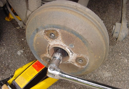
Undo the bolt on the front of the brake drum with a TX30 bit. Release the handbrake before you try and remove the drum!


Pull the driveshaft out of the back of the hub. You may need to pull the De Dion tube towards you to make enough space. Make sure the car is supported well before you do this.


You can now access the four E14 bolts on the back of the hub.


Remove all four bolts, hold the backing plate for the rear brake and carefully pull the hub free from the car.


The hub has a lip on the back which stops it falling off as you remove the bolts.


As the hub becomes free, we used one of the bolts we removed to hold the brake backing plate to the axle. In this way, you avoid putting stress on the brake lines.


You can now replace your old hub with the new one.


the hub doesn't have a particular 'way up'. Just ensure you don't trap any dirt as you bolt the new hub through the axle and rear brake base plate.


Reassembly is the reverse of removal.

Torque settings:

E14 hub mounting bolts: 65Nm.
TX30 brake disk securing bolt: 6.5Nm.
13/16 AF Driveshaft Bolt: 30Nm + 90°.
Wheel bolts: 110Nm.

Wednesday, 28 June 2017

how to change a front wheel bearings

Step 1 . WHEEL BEARING REPLACEMENT: GETTING STARTED

These instructions apply to bearings in a non-drive wheel. In other words, if your car is front wheel drive, we're talking about the rear bearings. If it's rear wheel drive, you'll be replacing the front wheel bearings.

How do I know if I need new wheel bearings? Most of the time we don't even know that they need service. We just drive and never think about them. Most car manufacturers recommend a wheel bearing clean, inspection and repack every 30,000 miles. This is usually done along with the front brake service. They need to be replaced when there is scoring and pitting or they become noisy.

What you'll need:

  1. Large adjustable wrench and Channelocks
  2. Bearing race driver tool or various size punches
  3. Socket and ratchet set or assorted wrenches
  4. BFH
  5. Lots of rags
  6. New wheel bearings
  7. Wheel bearing grease
  8. New cotter pin
  9. New grease seals
  10. Wheel blocks
  11. Safety glasses
  12. A jack and a pair of jack stands
  13. Rubber gloves (Optional)

Make sure that your car is parked on a level grade, rather than on any sort of hill or inclined driveway. Jack up the car and place your jack stands under the frame to support the vehicle. Block the rear wheels to prevent rolling. Set the parking brake and if you have an automatic transmission, put in Park.

Step 2. WHEEL BEARING REPLACEMENT: REMOVING THE OLD WHEEL BEARING


In most cases, you will need to remove your disc brake calipers and caliper bridge to remove the rotor. See Replacing Your Disc Brake Pads for more information on this. If your car has drum brakes, ignore this step.


  • First, remove the bearing cap. This is a press fit and to remove it grab it with your Channelocks and work it back and forth until it pops off. Be careful not to crush it as you remove it.
  • Once the cap is off you will see a cotter pin, Remove the cotter pin and remove the retainer ring. If your vehicle has a castellated nut, you will not have a retaining ring.
  • Using your Channelocks or adjustable wrench, remove the nut from the spindle.
  • Now remove the outer wheel bearing and washer and lay it aside.
  • Slide the rotor or drum off the spindle. This may be difficult, but it will come off. Don't worry about hurting the grease seal; we're going to replace it anyway.
  • Now that the rotor or drum is off, use a suitable tool to remove the grease seal and take out the inner wheel bearing.
  • Using some of the rags wipe all the old grease from inside the hub.
  • Now we need to remove the bearing races from the hub. Take a punch with a flat narrow tip and place it on the back of the race. Most hubs have gaps in them to expose the back of the race to make removal easier. Tap the race out, alternating from side to side so it comes out evenly and doesn't get cocked in the hub. Once it's out, flip the rotor or drum over and do the same for the other race.

When both races are out, clean the inside of the hub with some rags. Also make sure the spindle is clean as well. You can even use some carburetor cleaner to do a really good job of cleaning. From this point on cleanliness is important. You do not want any dirt, sand or metal chips inside the hub.

Step 3. WHEEL BEARING REPLACEMENT: GREASING IT ALL

Now that everything is nice and clean, let's put the new races and bearings in.


  • Take one of the new races and coat the outside with some wheel bearing grease. This will help it slide into the hub. If you have a race driver, select the proper size and tap the new race into the hub. Make sure you drive it in evenly and do not cock it. If you don't have a race driver, use your hammer to tap the outside of the race to get it started making sure you tap evenly around the race. When it is flush with the hub, use your flat narrow punch and drive it in the rest of the way. Make sure it is fully seated. The sound of the tapping will change when it's seated and you can look from the other side to visually confirm this.
  • Do the same for the other race.
  • If you don't have a bearing packer, you will need to pack them by hand. Put a glob of wheel bearing grease in the palm of your hand. Slip the wheel bearing on your index finger like a ring with the wide end facing out. Then tap the bearing into the glob of grease until you see it coming out the other side. When you see it come out turn the whole bearing, don't just rotate it on your finger, and repeat the procedure until the whole bearing has grease coming out the other side. Repeat this for the other bearings.


Step 4. WHEEL BEARING REPLACEMENT: REASSEMBLY


  1. Now that we have the races installed and bearings packed, we can put everything back together. Starting with the inner bearing put a bed of grease on the surface of the race and then push the inner wheel bearing into it. Take the new grease seal and tap it into place, don't bend or distort it. You can use a small block of wood to help.
  2. Put a coating of grease inside the hub between the two races and on the spindle -- too much is better than too little. If any moisture should happen to get inside, the grease will keep the metal from rusting.
  3. Slide the brake rotor or drum straight onto the spindle. It should slide on easily. If it doesn't, the bearing is cocked a little. Slide it off and make sure the bearing is sitting flat and try again.
  4. Once it's on, grease the outer race and slide the outer wheel bearing on. Slide the washer on. The washer will probably have a tab that will align with the spindle, make sure that you line them up when you put it in.
  5. Place the nut on the spindle and tighten it by hand until it won't go anymore. Spin the rotor or drum a few times back and forth and then tighten the nut more by hand. This insures that the bearings are seated. Do it a couple of times until you can't get it any tighter by hand.
  6. Now tighten the nut ¼ turn, no more than 16 foot-pounds. If you have a castellated nut, line it up with the hole going through the spindle. Install a NEW cotter pin. If you have a retaining ring, place it on the nut and install the pin. Never reuse the old cotter pin and make sure you use it.
  7. Put a small blob of grease on the inside of the dust cap and tap it into place, being careful not to crush it. Make sure it is fully seated.
  8. That's it, you're ready to roll nice and smooth!


Thursday, 22 June 2017

How To Repair Damaged Nuts and Bolts

A rethreading kit is an important part of any automotive toolbox. Use it to restore stripped threads on old, rusty nuts and bolts when you don't have time to search the stores for a replacement.

Start by finding the thread count.


Photo 1: File threads
Reset the threads with a thread file before screwing on the rethreading die.


Photo 2: Rethreading kit
Rethreading kits are available at auto parts stores and online. Buy a full set for both metric and SAE nuts and bolts.


Photo 3: Tap

Use a rethreading tap on nuts and threaded holes.


Photo 4: Rethreading die

Clean rusty or stripped threads with a thread restoration die.


No matter how careful you are when you reinstall old rusty nuts and bolts, someday you're going to strip some threads. Of course it will happen on a critical bolt, on a Sunday night when all the stores are closed. That's when a thread restoration kit pays for itself. A full set (metric and SAE) will quickly put irreplaceable and hard-to-find nuts and bolts back into service. The rethreading tools look like traditional taps and dies. But instead of cutting new threads, they reshape them to original condition.

To restore bolt threads, start by finding the thread count (SAE) or pitch (metric). Hold the thread file against the bolt threads until you find the size that matches. Clamp the bolt in a vise, engage the thread file grooves with the bolt threads and push the file (Photo 1). That “resets” the threads enough so you can screw on a rethreading die (apply a few drops of oil first). Use a rethreading tap to restore threads on nuts or threaded engine component holes. Don't try to rethread the entire bolt, hole or nut in one operation. Insert the rethreading tap or die and rotate a few turns, then back it off a full turn. That will dislodge the debris from the teeth.